
An ancient vacuum diode
image source

An ancient vacuum diode
image source
Robots almost universally employ electricity for command, control, and at least one stage of actuation. Shunting all this electricity around is the job of electronics. An extremely large range of pre-manufactured, standard commodity components are available. These range from discrete components like resistors, capacitors and transistors; to small-scale integrated circuits such as op-amps, logic gates, motor controllers, and timing chips; to large scale integrated components like memory chips, digital RF receivers, coder/decoder circuits, and communication protocol handlers; to full-blown microprocessors involving billions of transistors on a chip. Even complete computer systems are sometimes considered as modular units. Highly programmable systems comprise a whole set of fields. This section summarizes some basic information about the lower end of the spectrum useful to the robot builder.
Even the most complex electronic systems are composed mostly
from just a handful of basic components.
Making the final jump to macroscopic actuators usually involves power levels
that must be supplied by discrete-component systems, so some
familiarity and facility with these constituents is needed by robot
constructors.
The five fundamental components are resistors, capacitors, inductors,
diodes, and transistors.
Most electronic devices are concisely describable in terms of these basic units,
(and are often actually constructed from them).
But before we get to the components, a word about numeric values. If you've worked with electronic components at all, you may have noticed that the values available seem a little strange. Sure, you can find a 10uF capacitor, but the next highest in your assortment may be not 20uF, but 22uF, and there's a 47uF cap, but not a 50uF. In fact, numbers from the series
10, 12, 15, 18, 22, 27, 33, 39, 47, 56, 68, 82, (100)
keep showing up whether it is ohms, farads, or henrys being specified. What this series represents is not a linear scale, but a logarithmic one, where each number is a constant multiple of the previous one. Such a sequence is a practical way of filling a range of many orders of magnitude "evenly".
This particular sequence is the closest one can come in whole numbers to filling the decade from 10 to 100 with values that increase by 20% each step. The solution turns out to be 12 steps per decade, each multiplying the previous value by 101/12 = 1.2115, or about a 21% increase. Such standard sequences are referred to as preferred numbers, and they are defined in many fields (not always with 12 logarithmic steps). The above sequence is referred to as the E12 sequence (for Electronic, 12-step), which is part of the international electronic standard IEC 60063. The same standard also contains E6 (every other member of E12) and E24, E48, E96, etc. with additional steps for 10%, 5%, 2.5% intervals respectively.
You can read a lot more about the subject of preferred numbers in this
Wikipedia article.
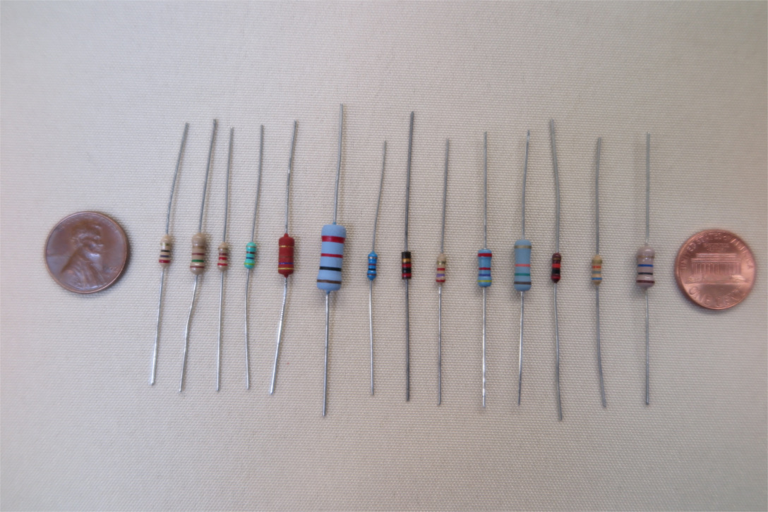
Small (1/8 - 1/2 W) Board-Mount Resistors
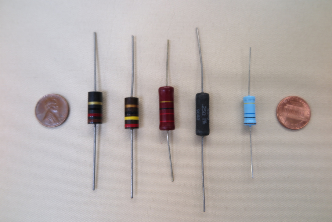
Larger (1-5 W) Resistors
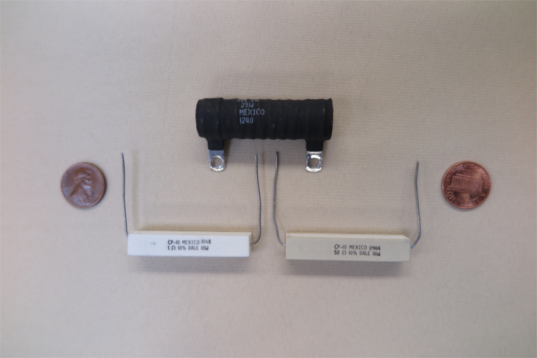
Power (10-25 W) Resistors
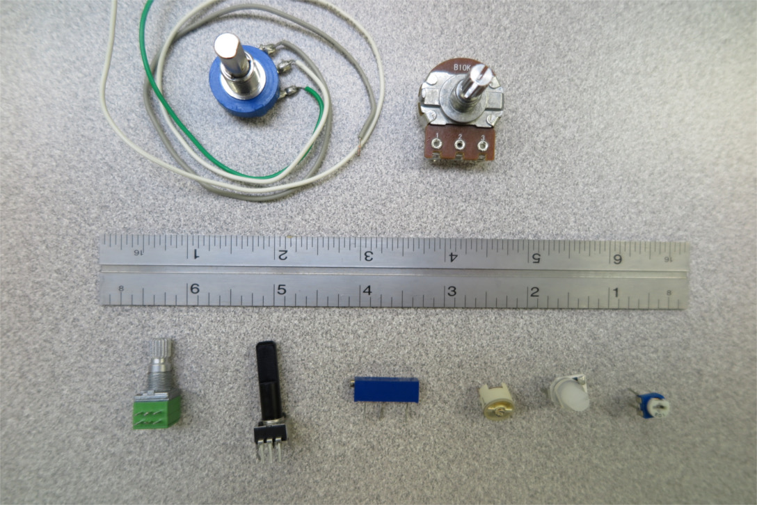
Potentiometers
A resistor resists the flow of electric current. Any material that permits the flow of elecricity has some degree of resistance. The resistors of electronics theory are idealized units where the flow of current is linearly proportional to the voltage across the unit. This behavior is encapsulated in "Ohm's Law"
V = IR
Where V stands for voltage (in volts) I for current (in amperes) and R for resistance (in Ohms).
Ohm's law is a reasonable approximation to actual behavior in many situations, for example, current running through a long wire. It is an even better approximation when commodity resistors are employed. These devices are specially designed to match the theoretical model. They are useful because the model is linear, and we know how to solve linear systems. Thus we can create composite devices with very predictable behavior.
Resistors in series simply add their resistance:
Rtot = R1 + R2 + ... + Rn
The same current flows in each resistor, and the voltage is divided proportional to the individual resistances.
Resistors in parallel add reciprocally:
1 / Rtot = 1 / R1 + 1 / R2 + ... + 1 / Rn
The voltage is the same across all the resistors, and the total current is divided according to the reciprocal of each resistance.
 |
 |
| Resistor, Rheostat, Potentiometer | IEC Representation |
Aside from the resistance, the most important characteristic of a resistor is its power handling capacity. A resistor dissipates energy as heat. If you run too much current through a resistor, it will get hot and burn up, possibly ruining your day. The power dissipated in a resistor is specified in units of watts, and given by
P = VI = I2R = V2/R
Where V is in volts, I in Amps, and R in Ohms. You can use whatever formula is most convenient given what you know about the situation.
In general, steady state power dissipated in a resistor should be well below its rating. It is good practice to use a safety margin of at least a factor of 4, except possibly in special power applications where you are up against the limits of available components. Pulsed power can exceed the resistor rating; exactly by how much and for how long depends on the resistor construction and other factors. Data sheets sometimes provide some information on surge handling.
The small, colorful resistors you see on circuit boards are mostly 1/4 watt though some are 1/8 watt. The bigger-looking versions are 1/2 or 1 watt. Larger "power" resistors from 2-20 watts look like white boxes, and usually have a printed resistance value rather than a color code. The small resistors are for signal handling applications, and not suitable for use in a circuit driving anything except an LED or very small motor. Limiting current in a larger motor if done resistively, usually requires a power resistor. Power resistors can produce a surprising amount of heat, so you should keep this in mind.
Small resistors are often marked with the famous color code to indicate their resistance. The different colors indicate decimal digits with black = 0, brown = 1, red = 2, etc. up through white = 9. Generally there are three (sometimes 4 for high-precision) color bands indicating the numeric resistance value. The first two (or three in high precision) are digits, and the third is a number of zeros to follow the digits, Thus red, red, orange is 22 000 or 22K Ohms. An additional gold or silver band on low-precision resistors indicates precision of 5% or 10%. On high precision resistors, a different color code for precision is used in the 5th band. This code is a bit confusing, for example red = 2%, brown = 1%, green, = .5% ... Best to look it up.
Variable resistors are available, often in the form of three-terminal potentiometers. Most of them use a sliding contact on a coil of resistive metal. They are often used for tuning circuits to precise values. They are useful in robotics as (somewhat imprecise) position indicators.
Resistors are made using several technologies. Small, low-power resistors are usually metal- or carbon- film devices. These consist of a thin layer of resistive metal or conductive carbon (graphite) that is plated over a cylindrical core, and etched with a spiral pattern to provide a longer current path. This layer is protected with a coating, usually ceramic. Power resistors are usually coils of resistive wire protected by a refractory ceramic housing.
A photoresistor, sometimes called a photocell, is a special device with a resistance that drops when it is exposed to light. The most common type is made with cadmium sulfide. They are inexpensive, and are frequently employed in simple light-detecting circuits. They are less sensitive, and much slower to respond than other light-detecting devices such as photo-diodes and photo-transitors. Typically response times are tens of milliseconds. Photcells are characterized by their dark state resistance, typically between 100K ohms and 10M ohms, and by their illuminated state resistance, under some standard illumination. Typically illuminated resistance resistance at 10 lux (which corresponds to dim, indoor lighting) is 10 to 100 times lower than dark resistance.
Some devices that might seem reasonable to model as resistors are not.
For example, the filament of an incandescent light bulb has a resistance
that increases rapidly as it heats up.
As a result, when a light bulb is turned on, it draws a transient
startup current several times the steady state.
This can burn out system components if not designed for.
Motors should not be modeled as resistances at all.
The current at a given voltage can vary by two orders of magnitude depending
on the motor load and the speed.
It can even reverse under some conditions.
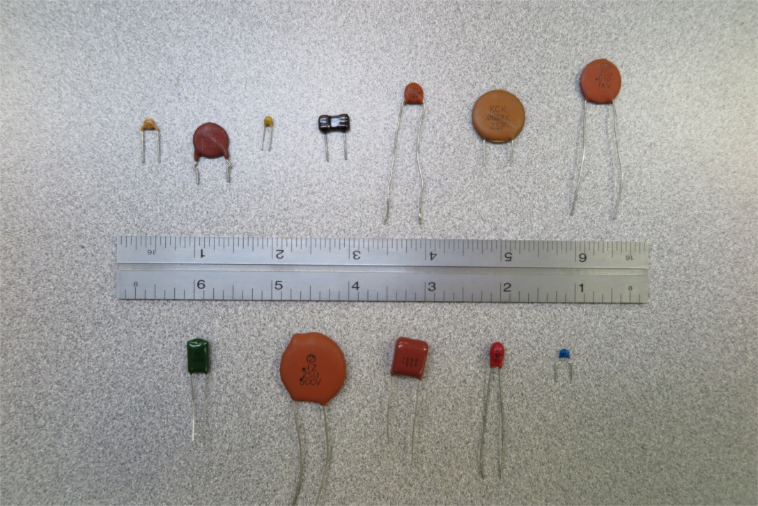
Unpolarized Capacitors
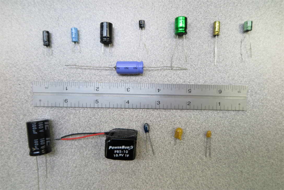
Polarized Capacitors
A capacitor is a device that stores electrical energy by charge separation. Conceptually a cap can be thought of as a pair of conducting (metal) plates with a thin layer of insulating material between them. If a voltage is applied across the plates, the plate on one side will take on a plus charge, and the plate on the other an equal negative charge in an amount sufficient to create an electric field that counters the applied voltage. The smaller the gap, the more charge it takes to produce a given voltage.
Capacitance, usually denoted by C is measured in farads. One volt across one farad produces one coulomb of charge separation. An ideal capacitor is described by the following linear relation.
Q = CV ⇒ I = C dV/dt ⇒ V = ∫ I dt / C
Where Q is the charge (coulombs), C is the capacitance (farads), and V is the voltage (volts). The second form in terms current I (amperes) through the capacitor is obtained by differentiating the first with respect to time. Note that capacitors do not "store charge" in the sense that they contain unbalanced positive or negative charge. Current in equals current out just like any other electronic device. But they do develop increasing voltage as current is pumped through them, as illustrated by the third (integral) form.
Capacitors in parallel add their capacitances like resistors in series.
Ctot = C1 + C2 + ... + Cn
The voltage is the same across all the caps and should not exceed the lowest rating in the combination. Larger capacitances can thus be obtained by parallel combination of smaller caps.
Capacitors in series add reciprocally like resistors in parallel.
1 / Ctot = 1 / C1 + 1 / C2 + ... + 1 / Cn
The voltage is divided proportional to these reciprocals, i.e. the most voltage is across the lowest capacitance. This effect can be used to produce a higher-voltage rated equivalent capacitor from a series combination of lower-rated caps. However some care must be taken. Variation from the nominal capacitance will cause variation in the divided voltages. A bigger problem is that even very small current leakage can cause stored voltages to accumulate in the system over time, eventually resulting in over-voltage failure of an element. If this failure produces a short circuit, the other caps can fail in a chain reaction. Because of this, caps in series must include a balance mechanism. The simplest method is simply to place a high value resistor in parallel with each capacitor, which allows unbalanced charge to equalize at the cost of a slight loss of storage time.
The energy stored in a capacitor is given by
E = ½CV2
Note the similarity to the kinetic energy and spring energy formulas from physics. This is not coincidental. All three formulas result from integration of a linear work function.
The other capacitor formula worth remembering is the characteristic time of a series RC circuit.
τ = RC
This is the time it take for the circuit to move about 2/3 (1 - 1/e = .63) of the way from its current to its ultimate value. It can be taken as rough indicator of how long charge is "imprisoned" in the capacitor.
 |
 |
 |
| Unpolarized Capacitor | Polarized Capacitor | Variable Capacitor |
Commodity capacitors are characterized by capacitance, maximum voltage rating, and by whether they are polarized or not. A polarized capacitor (electrolytics, and some others) can only be charged in one direction. An attempt to charge in the other direction can destroy the device (sometimes explosively); Maximum voltages should not be exceeded, even momentarily. It is good practice to use a capacitor with voltage rating twice the maximum expected to occur in the circuit.
A third characteristic is frequency rating. Physical capacitors have a limit on the rate at which they can be charged and discharged. With the exception of electric double-layer caps, sometimes called ultracapacitors, commodity caps are linear well into the KHz range. Frequency limits are thus not an issue in many robotics driver-end applications since the frequencies are fairly low. In the radio-frequency range however, frequency rating can be crucial. Electrolytic caps are significantly slower than many other types, and can be unsuitable in digital signal processing and RF communication circuits.
Commodity capacitors, per design, match the ideal model fairly well as long as they are run within tolerance. Traditional, small, board-mountable caps are available in a very wide range capacitances from picofarads up to 1/100 farads (10,000 microfarads), the larger values being almost exclusively electrolytics. If electric double-layer (ultra-capacitor) devices are included, values of several farads are available in small packages. Much larger values are available in "can" capacitors, and arrays.
Variable capacitors are available, usually in very low capacitances. The simplest utilize sets of plates that interlace like a half-shuffled deck of cards, with insulating material (or air gaps) between the plates. The capacitance is varied by changing the overlap of the interlaced sets, usually with some rotary mechanism. They are most often used for tuning RF oscillator circuits.
Many different types of capacitors are available, each with its own set of characteristics. Some of the most important are listed below.
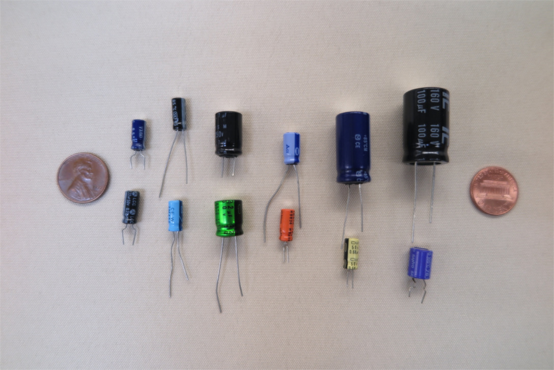
Small Electrolytic Capacitors
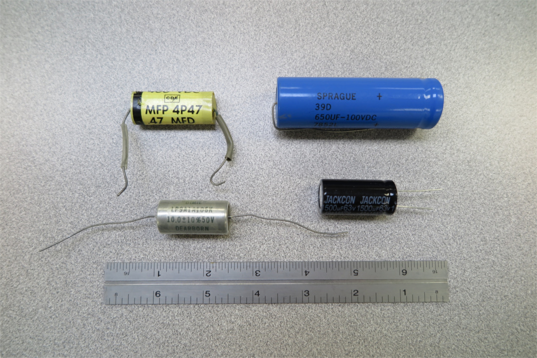
Medium-Sized Electrolytic Capacitors
Aluminum electrolytic caps are inexpensive and have large capacitance for their size (high volumetric efficiency). They generally look like fat cylinders with either axial or radial leads. Internally, they consist of thin aluminum foil, usually micro-textured for additional surface area, alternating with a porus (paper) separator, wound into a cylindrical roll, and immersed in a conductive electrolyte (e.g. aqueous boric acid with various additives). The exact composition of the electrolyte is crucial to good performance, and the formulas are generally trade secrets, though I expect a good chem lab could figure out the recipe in fairly short order. The foil is the "+" terminal (the anode), the liquid the "-" (the cathode). In operation, a very thin, insulating layer of oxide is produced and maintained on the aluminum surface by the electric potential. The high available capacitance is due to the extreme thinness of this layer, which may be only a few microns.
Board mountable elecrolytics are commonly available from .1 uF to 10,000 uF, with larger values available in "cans". Voltages range from 5V to a few hundred volts. Frequency response is generally good up through low kiloherz, but they may be unsuitable for RF applications. They are polarized devices and may be destroyed, sometimes explosively, if charged in the wrong direction. Consequently they should not be used in AC applications. An unpolarized device may be constructed by wiring two electrolytics back to back in series.
Electrolytics are less durable than some other capacitors because the liquid electrolyte can evaporate over time, especially at elevated temperatures. The seals are usually pretty good, and electrolytics can operate for decades. On the other hand, failure of an old electrolytic cap is a common reason for electronic device failure.
So-called tantalum capacitors are technically electrolytic in the sense that they are polarized devices and they have an ultra-thin dielectric oxide layer produced and maintained by an electrochemical reaction. However, they don't have a liquid component that can evaporate or leak, and so are much more durable than aluminum electrolytics. Structurally they consist of a sintered tantalum sponge, surface treated to produce a dielectric layer of tantalum pentoxide, and infiltrated with a manganese dioxide solid conductor to provide the cathode. Tantalum caps have a very high volumetric efficiency, and excellent durability and stability. However, tantalum is an expensive metal (currently about $1/gm), and the capacitor manufacturing process is complex making tantalum capacitors relatively expensive. Thus they are typically used only in applications where the durability and volumetric efficiency are worth the cost (e.g. cell phones).
Board-mountable units are commonly available from about .1uF to a few hundred uF, and operating voltages up to 50V. The most common form factor is a slightly flattened ellipsoid with a pair of radial leads, one marked with a "+".
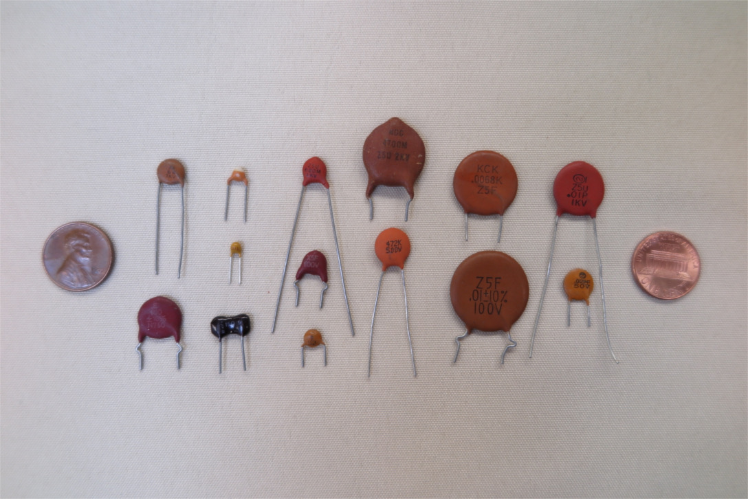
Small Ceramic Capacitors
Ceramic capacitors consist of two or more thin layers of metal embedded in a ceramic dielectric package. In the classic through-hole they look like a flat disk or button with two radial leads. More modern multi-layer designs for surface-mounting look like small blocks. They are unpolarized, durable and heat resistant, can be constructed to withstand thousands of volts. Ceramic caps come in two types referred to as class I and class II. Class I is the older technology, and uses ceramics with ordinary dielectrics properties, often based on titanium dioxide. These capacitors have excellent linearity, durability, and high-frequency performance. They are frequently used in RF applications when signal stability is critical. On the down side, their capacitance tends to be relatively small. Board-mountable units range from a few pico-farads to about 10 nano-farads.
Class II ceramic caps use exotic dielectrics known as ferro-electric materials. Barium Titanate is a well known example. They have a much higher volumetric efficiency than class I devices, but sacrifice accuracy and linearity, and exhibit aging effects. Capacitances range from nano-farads to a few microfarads in very small packages whose construction lends itself to surface-mountable devices. They can substitute for small electrolytics, which are more difficult to make in tiny, surface-mountable forms. Board-mountable units are commonly available up to about 10uf.
Small ceramic caps are frequently labeled with a 3-digit code where the first two digits followed by the number of zeros given by the third digit gives the capacitance in picofarads. For example 473 would be 47,000 picofarads, or 47 nanofarads. Other codes are also employed, both for capacitance and other factors such as temperature stability. Bottom line is the labeling of ceramic caps can be a bit cryptic, and interpretation may require reference to the manufacturer's datasheet.
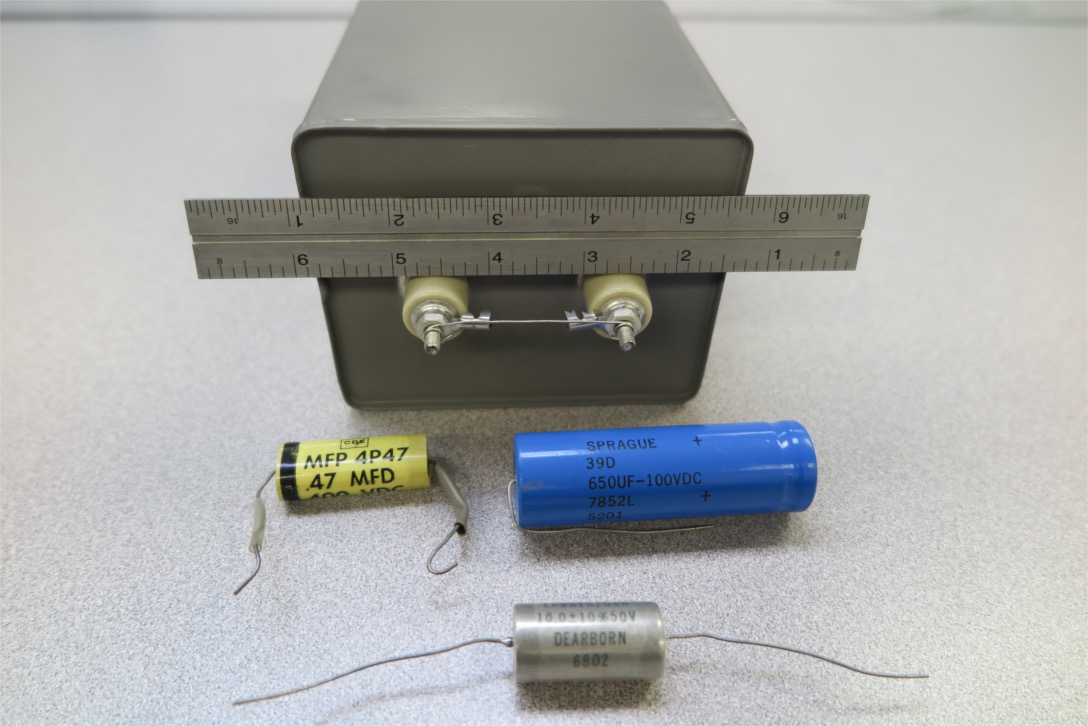
A Large Film Capacitor and Others
Film capacitors consist of multiple layers of thin aluminum foil separated by thin insulating film, usually various polymers, but occasionally specially treated paper or other substances. They are non-polarized, durable, linear, and can be made to operate at several thousand volts. They have higher operating frequencies than many electrolytics, but not as high as class I ceramics. Their capacitance can be specified with high accuracy. They have low volumetric efficiency compared to electrolytics, but significantly higher than class I ceramic units. They tend to be used when accuracy, AC operation, and linearity are important and more capacitance is needed than can be provided by class I ceramics.
Board-mountable units are commonly available from 1nF to 1uF at up to several hundred volts, at prices comparable to electrolytics of equivalent volume (but much higher capacitance). The most common form factor approximates a rectangular prism. Much larger "can" units are available, with higher capacitances and operating voltages up to tens of kilovolts. These tend to be quite expensive.
Supercapacitors, or ultracapacitors, most commonly implemented as electric double-layer capacitors or EDLCs represent a huge leap in capacitor technology. The basic technology dates from the 1970s, but inexpensive, commodity devices are a relatively recent development. Supercapacitors have a volumetric efficiency 3-4 orders of magnitude greater than aluminum electrolytics, and for the first time allow farad-scale capacitances in board-mountable devices. They are durable and relatively inexpensive. On the negative side, the charge/discharge time factor is on the order of a second rather than milli- or microseconds, and the individual cells are limited to about 1-2 volts. This means that for most applications, the slightly touchy issue of connecting capacitors in series to handle higher voltages must be dealt with.
In some sense, supercapacitors fill a gap between rechargable batteries and more traditional capacitors. They can charge and discharge 3 orders of magnitude faster than batteries, but have only about 1/10 the energy density. On the other side, they can have 1000 times the energy density of electrolytic caps, but discharge 1000 times more slowly. They are far more durable than batteries, and can be charged and discharged hundreds of thousands rather than hundred of times, but unlike most traditional capacitors, there is some slow degradation with use. Most supercapacitors have significant internal leakage. With optimized configuration, they can hold a charge for periods on the order of a few days, but can't match batteries for long-term energy storage.
The most common supercapacitors are carbon-electrode, electric double-layer capacitors. The basic principle of operation is the formation of a molecular-scale charge separation layer at the interface between a charged solid electrode and a liquid electrolyte. This layer has a characteristic thickness on the order of a few angstroms rather than a few microns for the oxide layer in standard electrolytic caps. If two electrodes are placed in the same electrolyte and kept from touching, the result is a capacitor with extremely small effective charge separation. The thinness of this layer accounts for most of the high capacitance. The rest is due to the development of solid electrodes with extremely large surface areas. Current EDLCs use carbon electrodes formed by carbonizing coconut husk material. The billions of carbonized cell walls produce a porous material of exceptionally high effective surface area per volume. The process essentially exploits the ability of biological processes to produce bulk nano-structure.
Although abstractly, EDLCs have symmetrically functioning positive and negative electrodes, the different chemistry of the positive and negative sides required different optimizations for performance. Hence EDCLs are generally polarized devices.
EDLCs are available as single cells, or as prewired and pre-balanced arrays for higher voltage applications. Board-mountable components are available in the farad range for a few dollars, and larger units up to a thousand farads or more at proportionately greater expense. Some arrays utilize back-to-back configurations of the polarized elements, which means they are initially unpolarized. However, once charged in a given orientation, such arrays should not be reversed. Balancing usually entails introducing additional charge leakage into the array. Passively balanced arrays, which just strategically insert a high value bleed resistors across the elements may self-discharge in less than an hour. Actively balanced arrays employ more sophisticated charge sensing logic and semiconductor switches, but should still not be counted on to maintain a charge for more than a day unless explicitly rated for longer periods.
Supercapacitors are usually employed for medium-term, medium capacity energy storage. Applications include surged-power delivery for devices like intermittantly-used motors, and intermediate storage for power generation with rapidly varying inputs such as wind and solar intallations. They are used in electric vehicles with regenerative braking systems, and similar applications where power needs to be smoothed out for optimal charging and discharging of primary battery systems. They are sometimes used to implement short- to medium-term uninteruptable power supplies for critical applications. All in all, a cool new technology.
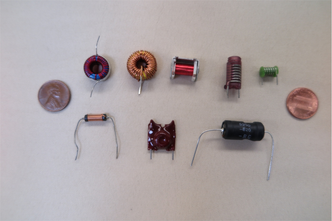
Small Inductors
Electric current flowing in any conductor produces a magnetic field. Magnetic fields store energy, hence as currents ebb and flow in a circuit, magnetic energy must be considered as part of the overall energy balance equation. Such inductive effects can be exploited for various purposes in an electronic circuit, and an inductor is a circuit element intended to produce effects purely due to stored magnetic energy. Since coils are an effective geometry for producing strong magnetic fields, inductors tend to be coils.
The main effect of an inductor in a circuit is to oppose change in the current flowing in it. This opposition manifests as a voltage across the inductor whenever the current is changing. The power represented by this voltage multiplied by the current is the energy flowing into or out of the magnetic field.
The behavior of an ideal, linear inductor is described by the equation
V = L dI/dt
where V is the voltage across the coil in volts, L is the inductance measured in henrys, and I is the current through the inductor in amperes. One way of looking at this is that a voltage placed across an inductor will cause the current to increase at a constant rate that is inversely proportional to to inductance. Like a farad, a henry is a very large unit on the scale of consumer electronics. Most board-mountable coils are measured in milli- or microhenrys.
Inductors combine just like resistors, i.e., inductors in series add linearly, and inductors in parallel add reciprocally.
The energy stored in an inductor is given by
E = ½LI2
Note the similarity to the capacitor energy equation and the kinetic energy
equation.
There is, in fact, an exact mathematical analogy between linear circuits with
inductors, capacitors and resistors, and Newtonian mechanisms with
masses, springs, and dampers.
Charge is analogous to position, current to velocity, dI/dt to acceleration,
and voltage to force.
Inductors are analogous to masses with mass L, and capacitors to
springs with spring constant 1/C.
Resistors are dampers.
The inductor equation is analogous to F = mA, and the
capacitor equation to F = kx.
As with a RC circuit, a series LR circuit has a characteristic time given by
τ = L/R
This is the time required for the current in a closed LR circuit to decay to 1/e = 37% of its initial value, or more generally, the time for the current in a LR circuit to change 63% of the way from its initial to its final value. Basically, the characteristic time is a rough measure of how long an inductor "ride" is.
A final formula worth knowing involves a series circuit loop containing both an inductor and a capacitor. Just like a mass on a spring, such a circuit will oscillate. The natural frequency (in radians per second) is given by
ω = √(1/LC)
The equation can also be expressed as a characteristic time
τ = √LC
Intuitively, this time is 1/2π or about 1/6 of a cycle, or the time for the oscillation to go from 0 to near its peak value.
In robotics, natural frequency is mainly important as something to stay away from. If a circuit contains LCR loops where the resistance is such that the characteristic LC time is both significantly longer than the the RC "prison" time and significantly shorter than the LR "ride" time, then unexpected, and probably bad oscillatory behavior may occur. There are somewhat complicated formulas that describe LCR behavior more accurately, but the three characteristic times are intuitive, and provide sufficient information to stay out of danger zones.
 |
| Simple Inductor |
The factors to consider when selecting an inductor are the inductance (of course), the maximum DC current rating, and the resistance. There is also a parameter called the self-resonant frequency. This is the natural frequency of the resonant circuit formed by the intrinsic capacitance of the device combined with its inductance. You want this to be many times higher (10x at least) than the highest frequency of importance in your circuit. This is usually only an issue in RF circuits.
Another parameter that is sometimes encountered is the Q-factor or quality factor. This is essentially the ratio of an inductor's lossless reactive impedance to its lossy (effectively resistive) impedance at some reference frequency. Intuitively, an inductor with a high Q-factor is acting mostly as an inductor. If given as a component parameter, the Q-factor is with respect to some test frequency (well below the self-resonance frequency) that can be taken as a good-performance upper bound for the device. Since losses increase with frequency, this value is understood as a minimum (i.e worst-case) Q-factor.
Board-mountable inductors are available from fractional nano-henrys, up through 100 milli-henrys or so. High-inductance board-mountable units tend to be wound with lots of very fine wire, and thus to have significant amounts of resistance (tens to hundreds of ohms) and limited current-carrying capacity (tens of milli-amps). Larger inductances, up through several henrys, are available; they tend to be bulky and resemble transformers. In fact, if you need a large, low-frequency inductor, a transformer with no load often makes a good one.
Variable inductors can be obtained over a wide range of values. The simplest employ a moveable magnetic core. Another design, encountered in high-inductance devices, utilizes a variable air gap in a nearly closed loop of magnetic material. Variable inductors are used for tuning oscillator circuits. They are also used in position-sensing devices, and are particularly valuable for this purpose because a moveable core does not need to contact the coil physically. This permits sensors that are sealed against high pressure, vacuum, or harsh chemical environments.
A particular variable inductive sensor known as a Linear Variable Differential Transformer or LVDT employs three coils with a moveable, coaxial core. The center coil is driven by an AC signal, and the outer coils are wound so the induced voltages cancel when the core is in the center position. Motion away from the center position produces a (nearly) linear change in output voltage. You can even build your own .
As mentioned previously, inductors are usually coils. These coils may be uncored (air core) or they may have an internal core consisting of a ferro-magnetic material, usually metal (iron) or a ferrite ceramic in order to increase inductance. The core may be a simple rod or drum, which can increase the inductance several times over the same geometry with an air core. It may also form a closed loop of magnetic material, which can multiply the inductance hundreds or thousands of times. Common closed core geometries are toroids (donut shaped cores), and figure-8 double loops, usually pieced together from several components.
Air-core inductors are linear and very stable, but they also tend to have very low inductances. They are usually employed in RF tuning circuits, where stability is important. Magnetic-core inductors can have high inductance in a small package, but they tend to be extremely non-linear, and exhibit saturation effects. Intuitively, ferro-magnetic materials provide an enormous amount of magnetization for a relatively small current up to a "saturation" value, beyond which increasing the magnetization requires increasing the current by amounts comparable to air-core devices. This behavior is exploited deliberately in inductors termed "chokes". These provide resistance to rapidly increasing current up to the saturation point, but then abruptly "open" at high currents. The non-linearity is cleverly exploited in a number of circuits, an important example being the elimination of AC transients from DC signals. Of course for lower currents, a choke can just be used as an inductance.
Iron cores are simple to make, but since iron is a conductor, it supports eddy currents that produce losses that increase rapidly with frequency. These can be reduced by using laminated construction, but in practice, iron-core inductors are useful only up to a few KHz. For higher frequencies, ferrite-core inductors are employed. Ferrites are ceramic materials are ferromagnetic without being conducting, and they can be used to make inductors functional through the RF range.
Motors contain intrinsic inductors. Big ones.
Inductors not only resist increasing current, they resist decreasing it.
If any kind of a switch in a current-carrying inductive circuit is suddenly
opened, dI/dt abstractly goes to infinity as the current stops flowing.
In practice, the voltage across the opened switch rises dramatically until
a path is found that permits current flow to dissipate the magnetic energy
resistively.
Even with a small inductance, this transient can reach thousands of volts.
With a mechanical switch, the path found is frequently an arc (the familiar
spark seen when a circuit is broken).
If the "switch" is of the semi-conductor variety, the result is frequently
destruction of the semi-conductor device.
Switching off your motor can destroy your circuit.
A circuit can be protected by placing a capacitor or an appropriately
oriented "free-wheel" diode across the inductor, possibly in conjunction
with a small resistor. Both arrangements give the current a path to continue
flowing when the switch is opened and to be gradually dissipated.
With a capacitor, a decaying oscillation is produced; with a diode,
a decaying DC current loop.
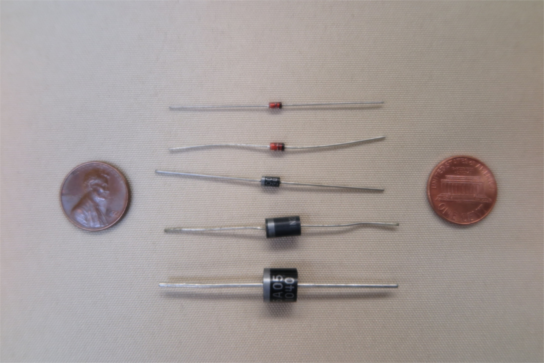
Various Board-Mount Diodes
A diode can be considered a one-way electric valve. Basically current can flow in one direction, but not in the other. Unlike resistors, capacitors, and inductors, diodes are non-linear devices. The ideal model is simple, but actual diodes differ from the model in ways that are both sometimes significant, and complex to describe.
An ideal diode allows current to flow without resistance from the anode (+ side) to the cathode (- side) in the so-called "forward bias" condition. In the "reverse bias" condition (- on the anode, + on the cathode) no current flows at all.
In actual diodes, the current in the forward bias condition is an exponential function of the voltage (with a small constant subtraction to make the current equal to 0 at 0 voltage) In silicon diodes, the forward voltage under useful operating operating conditions tends to be on the order of 1V (0.7V). This is a useful approximation because the exponential multiplier is on the order of 25mv, so any significantly higher voltage will burn out the diode, while a significantly lower one will yield a functionally zero current. In most applications, current in the forward bias condition is limited by other circuit components.
Under reverse bias conditions, the current is approximately equal to the small constant subtraction, which is known as the reverse bias current right up to a point known as the breakdown voltage, where the current starts increasing very rapidly with voltage. Operation in this regime may cause permanent damage to the diode. Special devices known as zener diodes are designed to be operated in the breakdown region and are used to limit or to clamp the voltage to the breakdown value.
Diodes can be placed in series if required to resist higher reverse voltages. The forward voltages add, so given a choice, you are generally better off using a single high voltage diode than several low-voltage ones in series. Diodes should not be wired in parallel to support higher currents without some sort of balancing resistance. The reason is that small differences in individual characteristics combined with the exponential current/voltage relation can result in most of the current being shunted through just one of the parallel diodes causing cascading failure of all units.
Light-Emitting Diodes or LEDs are so called because electrically and physically, they are semi-conductor diodes. They can be described and analyzed using the same models as their non-light-emitting cousins. However, they are generally employed for their light-emitting characteristics rather than their electrical behavior, and are hence functionally different devices.
 |
 |
 |
 |
| Ordinary Diode | Zener Diode | Schottky Diode | LED |
Commodity diodes are typically rated with respect to several parameters including forward voltage drop, maximum forward continuous current, peak reverse or holding voltage, reverse leakage current, and sometimes breakdown, or zener voltage. Other parameters that are sometimes of interest are recovery time and maximum surge current. Which parameters you pay attention to depends on what you want to do with the diode. Do you want a rectifier (a one-way valve), a voltage-limiting zener, or a light source?
For a rectifier, the most important characteristics are the peak reverse voltage which is the reverse bias the diode is rated to withstand, and the forward continuous current which is the maximum conducting current that can be sustained steady state. Good practice is to have the reverse voltage rating at least twice the maximum you expect to occur in your application, and the continuous current several times what you expect your typical maximum continuous demand to be (I'd go 4x-10x for most applications). Diodes operated at maximum rated current can get quite hot, so you often want to be more conservative on this axis than on the reverse voltage axis.
For some applications, especially low-voltage or low-power applications, the forward voltage rating may be important. This is usually defined as the forward voltage across the diode at its maximum rated current. For silicon diodes, this value tends to be between 1.0V and 1.5V. Special devices called Schottky diodes can have forward voltages less than .5V. LEDs have higher forward voltages than rectifier diodes, usually from 2V to 4.5V, depending on the color.
Diodes can tolerate brief surges of current many times higher than their continuous current ratings. The exact meaning of the surge rating must be looked up on device data sheet, but typically it refers to time periods on the order of milliseconds.
Recovery time refers to a period during which a diode that has been forward biased may conduct a reverse current before locking up. These times are usually tens of nanoseconds to a microsecond or so, and not a concern for typical discrete-component robot systems. In high power RF circuits and pulsed power applications however, the recovery time may be a significant issue.
A large number of different physical devices exhibit diode characteristics and have been used as diodes in electrical/electronic applications. Almost all of the diodes of interest for robotics however, are semi-conductor devices, so we will restrict the discussion to a small group of those devices.
Most rectifier and general purpose diodes are silicon p-n junction devices. Board-mountable components are available with reverse voltage ratings from 10V to several thousand volts, and current ratings from a few milliamps to several amperes. Forward voltage ratings are generally between 1.0V and 1.5V, with actual forward voltage in small-current applications of about .7V. They are compact, durable, and inexpensive; in quantity sometimes only a few cents per unit. Larger devices for industrial power applications can handle thousands of amps. These tend to be pricy.
Schottky diodes are metal-semiconductor junction devices. Common compositions include chromium, molybdenum, tungsten, or platinum against n-type silicon. They have a lower forward voltage, and significantly higher switching speeds than p-n junction diodes. Typical uses include low-power applications, where the smaller forward voltage can reduce power consumption; measurement devices, where the input signal may be small; and high frequency RF circuits. Forward voltage drops in low-current applications are .15V-.5V, compared to .7V for p-n junction silicon. Recovery times can be as low as 100 picoseconds compared to 10 nanoseconds for a very fast p-n junction. On the downside, Schottky diodes have higher reverse leakage currents than p-n junction diodes, and reverse voltages are limited to low values, typically 50V or less. They also tend to be a bit more expensive, though not hugely so.
The term Zener diode is often used as a generic reference to diodes that start conducting in the reverse direction at a relatively specific voltage, and can carry substantial reverse currents without damage. Technically there is a distinction between diodes that employ the so-called Zener mechanism to achieve this and avalanche-breakdown diodes that produce similar behavior, usually at higher voltages, with a different solid-state physical mechanism. For most robot applications, the distinction is not functionally significant. Zener diodes are typically employed in a reverse bias configuration, either to limit voltage to a safe value by providing a "relief valve", or to provide a stable reference voltage for a circuit. The novel parameter of interest is the Zener (breakdown) voltage, which can range from just under 2V, to over 300V. The Zener voltage can be fairly accurately controlled in the manufacturing process, and is very stable (sometimes less than .1%) for a particular device over a useful range of temperatures and input power/voltage variations.
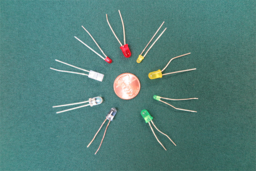
Light-Emitting Diodes (LEDs)
Light emitting diodes, or LEDs have traditionally been used as visual indicators and as components of photo-electric sensors. More recently, versions have been developed with sufficient output to be used for area illumination. Modern LEDs are available in a wide range of colors, spanning the spectrum from near infrared to near ultraviolet. A wide range of semi-conductor materials are employed to achieve these effects. Emission tends to be fairly narrow-bandwidth, and can be further modified by the use of intrinsic filters. This makes LEDs suitable as sources for photosensors as the sensor can be equipped with a corresponding narrow-band filter to reduce background signal. So-called "white" LEDs are composite devices consisting of a blue LED combined with a material that fluoresces over a relatively broad spectrum with an overall yellow appearance.
Electrically, LEDs behave like other diodes, and are characterized by the same parameters. They have higher forward voltages than signal diodes ranging from about 1.8V to 4.5V, and this voltage scales roughly with the energy/frequency of the emitted light. Thus a 1.8V device likely emits IR, and a 4V one blue or violet. The small indicator LEDs traditionally used on circuit boards usually have forward currents of a few 10s of milliamps. They should always be wired in series with a current-limiting resistor, otherwise you will burn them out.
Several optical parameters are associated with LEDs. The most obvious is color, which is usually specified with color words (red, green etc.) and in nanometers at peak wavelength. Most LEDs emit light directionally rather than uniformly in all directions. This is usually characterized as a viewing angle (e.g. 20 degrees) which is the full angle subtended by the cone of half-max intensity. Another parameter sometimes encountered is luminous intensity (intuitively brightness), usually specified in milli candelas, abbreviated mcl. This is a measure of the visible energy emitted per unit solid angle in the direction of maximum brightness. The exact physical definition of the unit is slightly complicated by the fact that as a measure of visible luminosity, different wavelengths are weighted by the human eye's sensitivity function. An ordinary candle emits roughly one candela in all directions. An LED with a narrow viewing angle will have a higher luminous intensity than one of equivalent power with a wide viewing angle, since the same energy is concentrated into a smaller total solid angle.
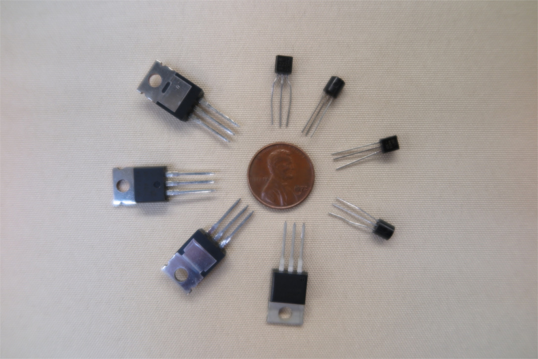
Board-Mount Transistors
Finally, we get to transistors. Transistors display complex behavior compared to linear components, and there are a lot of practical issues involved in employing them effectively in a circuit. Learning to do this is at least a full course worth of material, and we won't attempt to cover it here. In robotics, however, discrete transistors are typically employed fairly simply, usually as electrically controlled switches. More complex applications are generally handled by commodity integrated circuits of various sorts where the complexity of implementing useful and easily describable functionality has been wrapped up and hidden inside a chip. This section attempts to provide a summary of the transistor attributes most relevant to simple switching applications.
A classic transistor is a three-terminal solid-state device. Used in "standard" configuration, at the highest level of abstraction, it has two terminals that effectively provide a power current path, and a third by which a small signal can control that current. However, this abstraction only applies in certain parts of the space of ways in which signals can be applied to three terminals, and the different kinds of transistor differ significantly in what parts of the space such a model is valid. Making sure a transistor is operating in a regime where a desired model applies is generically referred to as "biasing the transistor". Transistors exhibit a variety of interesting behaviors in other parts of the signal space, and applications that exploit such behaviors are sometimes said to employ non-standard configurations.
Transistors can be broadly divided into bipolar junction transistors (BJTs) and field effect transistors (FETs). The latter group is further divided into junction field effect transistors (JFETs) and metal-oxide-semiconductor field effect transistors (MOSFETs). From our high-level view, the main functional difference between BJTs and FETs is that the control signal for a BJT draws a small, but design-significant current, while the control current for a FET, especially a MOSFET can often be considered to be zero.
More specifically, in standard configuration, a BJT is roughly modelable as a current-controlled current source with a high (e.g. 100) but not very stable or predictable gain. Similarly, a MOSFET can be approximately modeled as a voltage-controlled current source with A/V gain dependent on specific device and circuit. Like a diode, (and unlike a mechanical switch) a wide-open transistor generally has a minimum voltage of around 1V across the current path.
In each case below, the flow of current (+ to -) in the standard configuration is top to bottom.
 |
 |
 |
 |
 |
 |
| NPN Transistor | PNP Transistor | N-Channel JFET | P-Channel JFET | N-Channel MOSFET | P-Channel MOSFET |
The transistor type is often dictated by the circuit or application. Once the circuit has been designed and appropriate types have been determined, the primary factors to be considered when selecting transistors are the current-path breakdown voltage and the maximum continuous current. Other factors that may be important are power dissipation and switching time.
The current-path breakdown voltage is the maximum voltage that can be supported across the current path in the "off" state. The parameter is referred to as the collector-emitter breakdown voltage in a BJT, and as the drain-source breakdown voltage in a FET. Exceeding this value even momentarily can be expected to destroy the transistor. Generally breakdown should be at least twice the maximum voltage you expect to ever appear across the device.
The maximum continuous current is the greatest current that can be drawn through the device, steady state, in wide-open condition. The parameter is referred to as maximum DC collector current for a BJT, and as continuous drain current in a FET. Exceeding this for any significant time results in overheating and burnout of the transistor. Together with the breakdown voltage, this places limits on the power that can controlled by the device. Much greater currents can usually be supported as a brief surge, and data sheets sometimes provide details.
Power dissipation is important if the transistor is to be used in an amplifier application rather than simply as a switch. In many amplifier designs, the supply voltage not applied across the load is supported by the transistor. The maximum power dissipated in the transistor thus occurs not at full current/load voltage, but at about half these values, when both the current and the voltage across the transistor are relatively high. The power dissipated under these conditions must be kept under the rating for the device.
Switching speeds are typically a few tens to a few hundreds of nanoseconds, fast enough to be considered instantaneous for most mechanical actuation and sensing. This sets transitors apart from relays, which typically require at least several milliseconds. In RF and high-speed logic applications however, the switching speed may be a consideration.
Other parameters, such as the voltages that can be safely applied between the control terminal (base or gate) and the current-path terminals may be important in some configurations. In commodity transistors these are frequently appropriate for standard circuits when the primary parameters are appropriately chosen.
The pinouts on transistors are somewhat variable, even within a class such as small NPN BPJs. There are some widely-used configurations, but you should always check the data sheet for the particular device.
The first transistor was made using germanium, the semi-conductor element below silicon in the periodic table. Modern transistors are usually made from silicon, but special purpose transistors and transistor-like devices are produced using a wide range of semi-conductor materials. Manufactured sizes range from a few ten of nanometers (22nm technology appeared in consumer-level CPUs in 2012) switching nanowatts of power, to large industrial power modules capable of switching hundreds of kilowatts. Discrete transistors used in robot construction are usually relatively small devices, used for simple switching of a few milliwatts to a few watts. Power amplifiers and power drivers for motors are generally most conveniently purchased as integrated units rather than assembled from discrete components. The constructor interested in building his or her own amps or drivers might want to switch a few hundred watts, which is about the limit of board mountable devices when equipped with good heat sinks. But be warned. Designing a decent power amp or driver is not for the faint of heart or the mathematically unsophisticated.
Robot discrete-component circuits will seldom require anything other than ordinary silicon BJTs or MOSFETS, so we will limit this discussion to those devices. One exception might be experiments with unusual pulsed power actuators; these might employ more exotic devices like high voltage thyristors or IGBTs. If you are building such a bot, you had better do your research or risk becoming a sci-fi cliche.
Bipolar junction transistors or just transitors were the original three-terminal, amplifying, semi-conductor device. In modern design, several semi-conductor devices are available for amplifying or switching applications, but BJTs are still frequently employed. Compared to MOSFETs, the most frequently used alternative, BJTs have relatively low input impedance, and thus lower gain. They require non-negliglible input currents to operate. On the other hand, they are easier to position and model in linear regimes, and they can be manufactured to support many thousands of volts, whereas MOSFETs are limited to a few hundred. This makes them the choice in HV power applications.
Internally (and somewhat abstractly) , a BJT can be thought of as a three-layer sandwich of alternating N-type and P-type semiconductors. The two outside (bread) layers are connected to the current-path terminals, and the internal (filling) layer is connected to the control terminal. However it is not a symmetric sandwich; the doping, thickness, and geometry of the different layers are optimized for controlling currents in one direction. If you put a transitor in backwards, your circuit will not operate as expected, and you might smoke the transitor.
There are two possible sandwich configurations. One, NPN has a P-type filling between N-type bread, and the other, PNP an N-type filling between P-type bread. They basically act as electrical mirrors of one another. If you reverse the supply polarity in a transistor circuit and swap NPNs for PNPs and vice-versa, the circuit should remain functionally equivalent with all currents running in the opposite direction.
In standard switching configuration, NPN transistors are usually placed on the negative side of a load, and PNPs on the positive side. If only one kind of transistor is needed and a choice is available, the NPN form is often preferred. This is because for the same size and geometry, NPNs are usually faster and have lower internal losses than PNPs.
The technical terminology used to describe transistor terminals, is not very intuitive or instructive for the casual user, but it is frequently employed, so at some point you will probably need to sort it out for your device. The control terminal is called the base in both NPN and PNP devices. The current path terminals are the emitter and the collector. In standard configuration, the "+" terminal in an NPN is the collector. The "+" terminal in a PNP is the emitter. The names refer to who emits and collects majority current carriers in the microscopic model of operation, but that is not much help unless you are carrying those models around in your head.
As mentioned above, BJTs are complex, non-linear devices. For simple switching applications, a lot of the details can be ignored, since we are only interested in off-state and on-state extremes. For more complex amplifier circuits, transistors are biased into a regime where some linear model can be used over the range of functional interest. Finding the bias conditions however, may involve consideration of the non-linear characteristics. Designing transistor circuits from scratch is basically not for wimps. Fortunately, you can often look up some previously designed circuit and use scaling laws to adapt it to your application.
Metal oxide field effect transitors to give them their full name, are a more recent development than BJTs. They have very high input impedance; often the input current can be neglected. They can also be manufactured in extremely small form factors on planar surfaces. This combination of characteristics has made MOSFETs the dominent technology in VLSI computer chips. The high impedance also makes MOSFETs more sensitive to static elecricity than BJTs. A small spark can fry an unprotected IC, and even a power device. So take a bit of care when handling.
Abstractly, a MOSFET can be thought of as a pair of semi-conductor lilypads, not quite touching, made of highly-doped P or N material, floating on a pond of lightly doped semiconductor of the opposite type. For micro-model reasons, lilypads are named the source and the drain. The pond is termed the body or substrate Over the channel separating the lilypads is a thin layer of insulator (the oxide) and on top of that is a conductive metal plate known as the gate. Ordinarily no current will flow between the lilypads, but if a voltage is applied to the gate, it will induce a layer of opposite charge in the channel. If enough charge of the same sign as the carriers in the lilypads is induced, a current can flow between them, putting the MOSFET in the "on" condition. The necessary voltage is typically small - generally less than 2 volts.
Counting the pond, the MOSFET described has four terminals, and is symmetrical with respect to the lilypads. In practice, one of the lilypads is electrically connected to the pond, creating an asymmetric, three-terminal device. The pond-connected lilypad is the source; the other is the drain. In the standard switching configuration, a relatively small gate-source difference controls the flow of current between the source and the drain whose polarity with respect to the source is the same as the gate, but at considerably greater potential (up to a few hundred volts).
As with BJTs, MOSFETs come in two electrically mirrored varieties, called N-channel, and P-channel, according to the source-drain material type (and hence the channel conductors). N-channel devices tend to be used preferentially if there is a choice due to better speed and lower channel resistance for equivalent geometries.
The device described above is technically referred to as an enhancement-mode MOSFET due to the inducement of active current-carriers in the channel by the gate potential. There is a less common device termed a depletion-mode MOSFET, where the channel starts out conducting and the current carriers are forced out by the gate potential, shutting the current off. If you are running into these in a circuit, you probably need more edification than this note can supply, and should do some serious reading.
MOSFETs are useful in robotics when you want to switch a large current with a small signal; for example turning on a light with a direct output from a microcontroller. The light might draw an amp or more. Direct output from the controller would typically be limited to a few milliamps. A two-stage BJT switch would be needed to obtain sufficient current gain, but a high-impedance MOSFET could meet the need with a single stage.