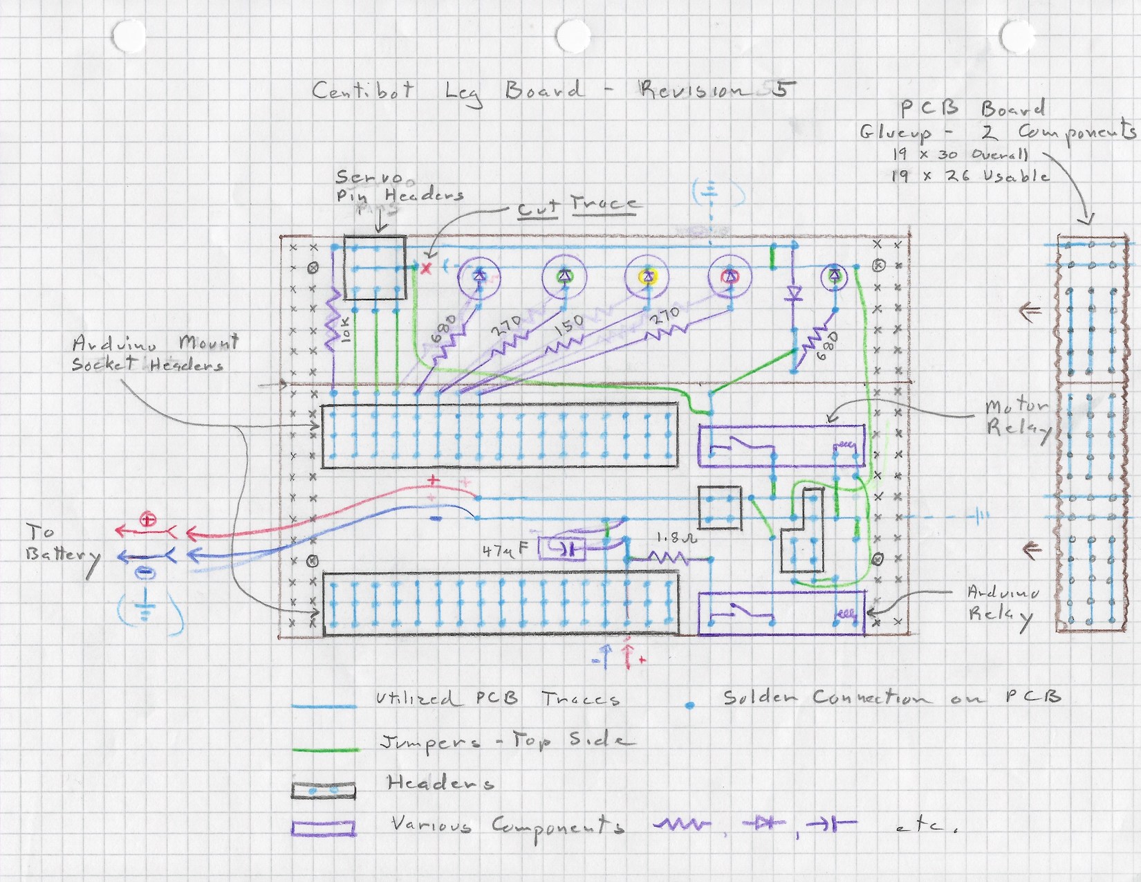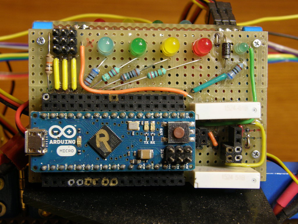
Arduino support board schematic


The boards are composed of two pieces of SB300 solderable breadboard. One is a full board; the other must be cut lengthwise on one side of the central power strip as shown in the schematic. Printed circuit board is a tough, epoxy-fiberglass composite. Cutting it with a bandsaw or handsaw will rapidly dull the saw, so don't do it. It can be cut by clamping in a vise along a line of perforations, and scoring along the perforations with a carbide tile scribe or utility knife, using the jaw of the vise as a guide. It may be necessary to score several times along the same line. You won't get many cuts from a utility blade before it is uselessly dull, but it's easily replaceable. The board can then be flexed back and forth until it breaks along the scored perforations. The edge can be cleaned up with a sanding block and 80-120 grit sandpaper, or using a belt sander. Make sure you wear a dust mask if using a belt sander, since the fiberglass dust is bad stuff to inhale.
The board segments are joined together by super-gluing to a .2" strip of some strong material along and under the left and right edges. We used strips of printed circuit board, but 1/8" ABS or polycarbonate plastic would work. This blocks two columns of perforations along both the left and right edges, but there is enough room left to lay out the circuit.
The schematic shows a trace that must be cut on the upper section so that it can provide power to the servo pin block on the left, and serve as a ground on the right. This is easily done using a small cutter on a rotary tool (Dremel), but it could also carefully removed with the corner of a small file.
The header blocks are made from standard strip header cut to length and glued together with CA superglue. Make sure that the alignment is precise. A piece of perf-board can be used as a guide in necessary. The CA glue should be applied sparingly with a toothpick or other tool. It should not squeeze out or slop over the edges. If it gets into the socket headers, which can happen from the top or from the bottom, , it will lock up the springy contacts inside and the socket will be useless.
Component soldering should start with the header blocks, since they will provide good landmarks for the other components. They can be held to the board before soldering by carefully applying a TINY bit of superglue. Be VERY careful not to get glue near the holes or the solder pins on either piece. Glue on the pins will inhibit soldering, and it can wick up inside the socket headers and glue the contacts, rendering the entire assembly useless. Components can also be temporarily held in place by careful use of tape, and other tricks.
After the header blocks are soldered in place, the boards should be carefully inspected for starved solder joints, solder-bridged traces, and other flaws, which must be corrected. It makes sense for someone other than the solderer to do the inspection.
Once the header attachment is complete and verified jumpers and other components can be placed and soldered. It makes sense to do this in batches, inspecting after each batch. Again, superglue or tape can be useful for holding components in place prior to soldering. As mentioned above, glue must be kept out of holes and off of leads, or it will interfere with making solder connections.
Remember that LEDs are polarized components. For round indicator LEDs, the "-" lead is indicated by a small flat on the plastic package, and the "+" lead is (usually) longer. Electrolytic capacitors are also polarized; the "-" lead is indicated by a stripe (often marked "-") on the package, and the "+" lead is sometimes longer. Note that the capacitor is under the Arduino mini-board when it is installed, and must be folded down to fit.

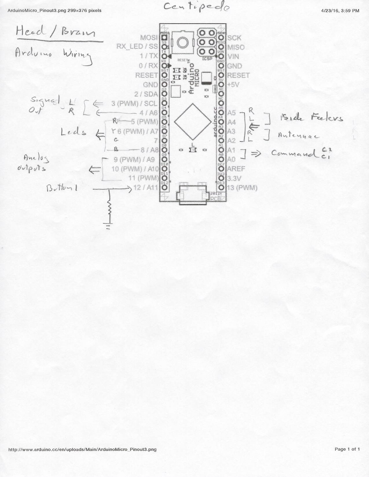
Arduino pinouts for use as central controllerbrain

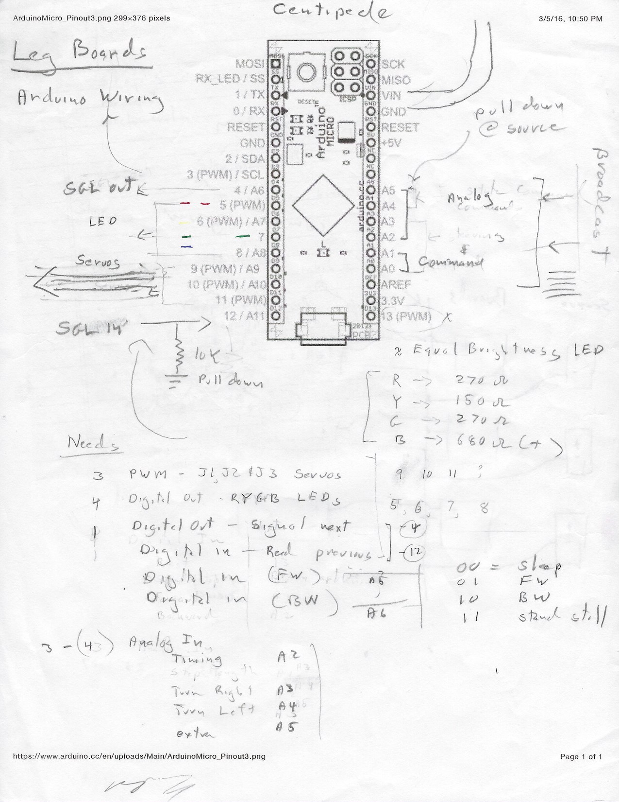
Arduino pinouts for use as leg controller
Copyright © 2016, Randal C. Nelson