This webpage contains information and resources that might be useful if you want run a similar workshop. It contains my (Sreepathi Pai) notes on the whole process.
The Open Source Turtle Robot is an excellent design with detailed instructions on how to put it together. As a newcomer to the Open Source Hardware Movement, here are more details on manufacturing the parts.
The PCBs were manufactured by OSHPark using their Prototype service. Electronic components were sourced through Digi-Key and Adafruit, per the Bill-of-Materials. Some substitutions were made to accommodate out-of-stock components (some IR LEDs and capacitors). Mechanical parts were sourced from McMaster-Carr. Order a few more parts than necessary to accommodate missing, lost, failed or destroyed parts. In my case, none of the parts failed or were destroyed, but I did have a missing part that prevented assembly of one robot.
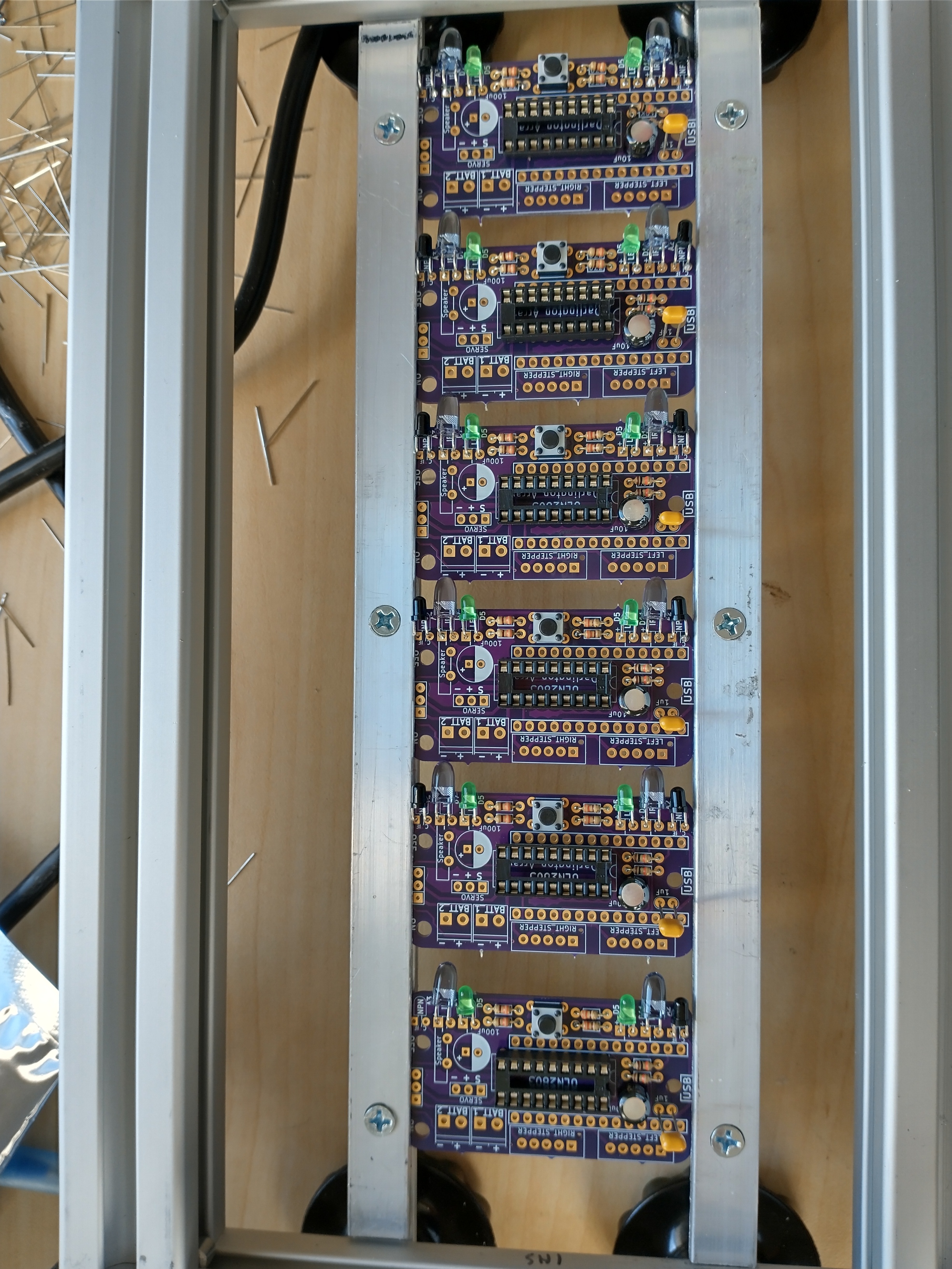
PCB assembly took me nearly 3 hours for the first one, though I hadn't soldered for many years. To speed this up, I searched for fixtures that could let me assemble multiple PCBs at the same time. Although these are available, their cost (around $500) was prohibitive. In the end, I built my own fixture based on a design from Nuts & Volts magazine. By judiciously sourcing from a local T-slot extrusion manufacturer (Framing Tech), obtaining the foam from a local shop (Fabrics and Findings), the metal sheet ("drop") from ExpressMetals outlet and using the fabrication facilities in Rettner Hall, I was able to quickly put the fixture together for around $100. Many thanks to Jim Alkins, our Shop Manager, whose help with the machining made short work of putting it together.
The finished fixture can accommodate 6 PCBs at a time though to be able to reach the components placed at the edge, leave OSHPark's V-cuts in place. Separate the PCBs, since otherwise soldering the LEDs and the MOLEX connectors is not possible. I removed the V-cuts by filing. Ultimately, I estimate the time to put together and test 13 PCBs at around 10 hours total by using the fixture.
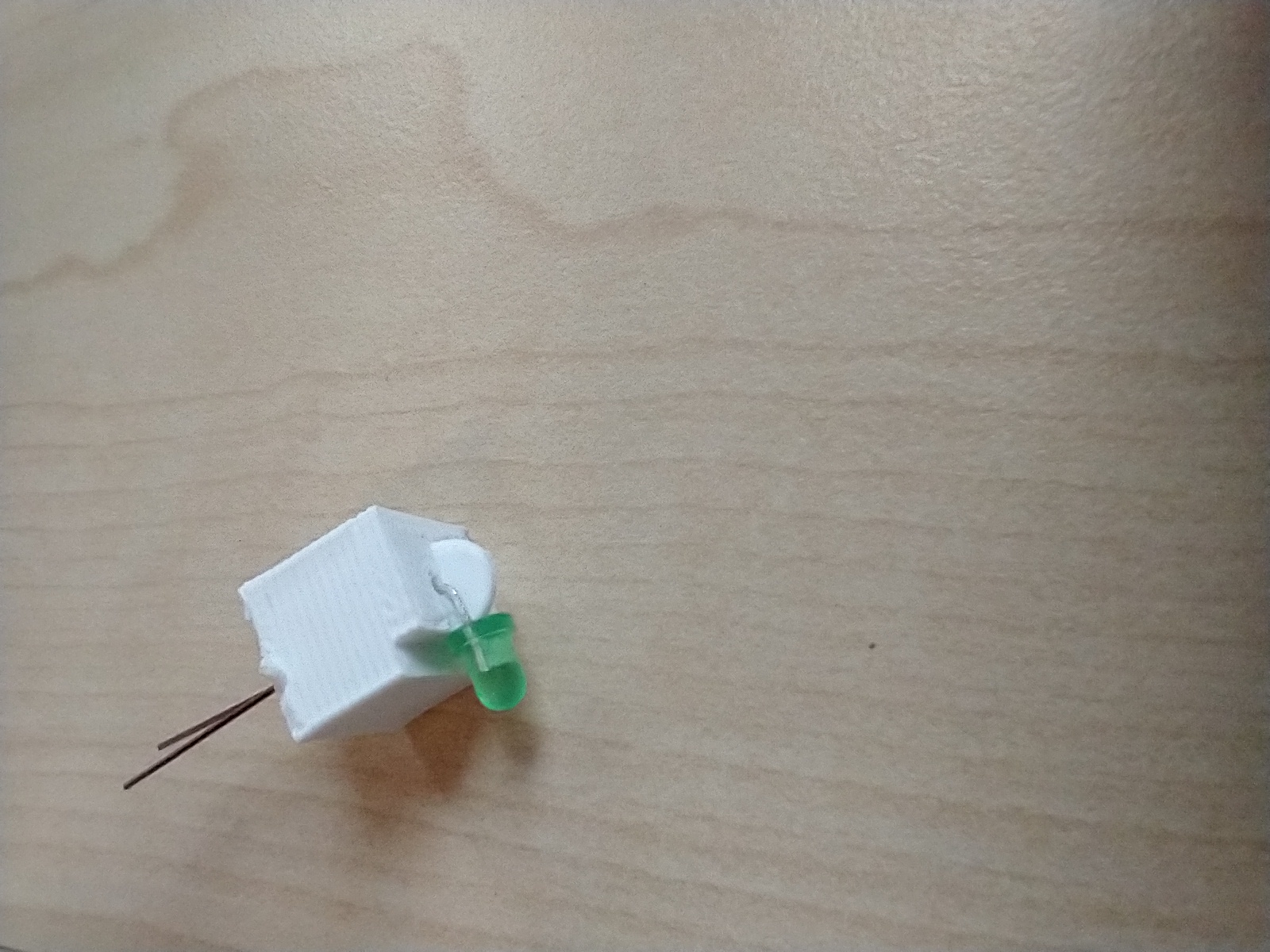
I also 3D-printed a part to help me bend the leads of the 6 LEDs on each PCB. Source code for the part in OpenSCAD., though you may want to use a bend_distance of less than 1mm.
The turtle robot uses four 3D-printed parts -- the chassis, a castor, pen holder, and the wheels. These were printed on a Stratasys F270 by Jim Alkins using ABS+. These were the most expensive parts of the robot (around $17 per robot), largely due to the use of proprietary filaments. Update: In 2023, I used my Voron Switchwire and inexpensive ABS filament (~$64 for two 1-kg spools) to print instead, reducing the 3D printed cost to less than $1 per turtlebot.
The wheel has a 3.25mm slot for the stepper motor axle that is 3mm, perhaps to accommodate undersized prints. This made it noticeably loose, which the set screws on the wheel did not fix. Therefore, I modified the wheel to have 3mm slots. Unfortunately due to version changes and my inexperience with FreeCAD, I was unable to restore some fillets, but that did not pose any functional issues.
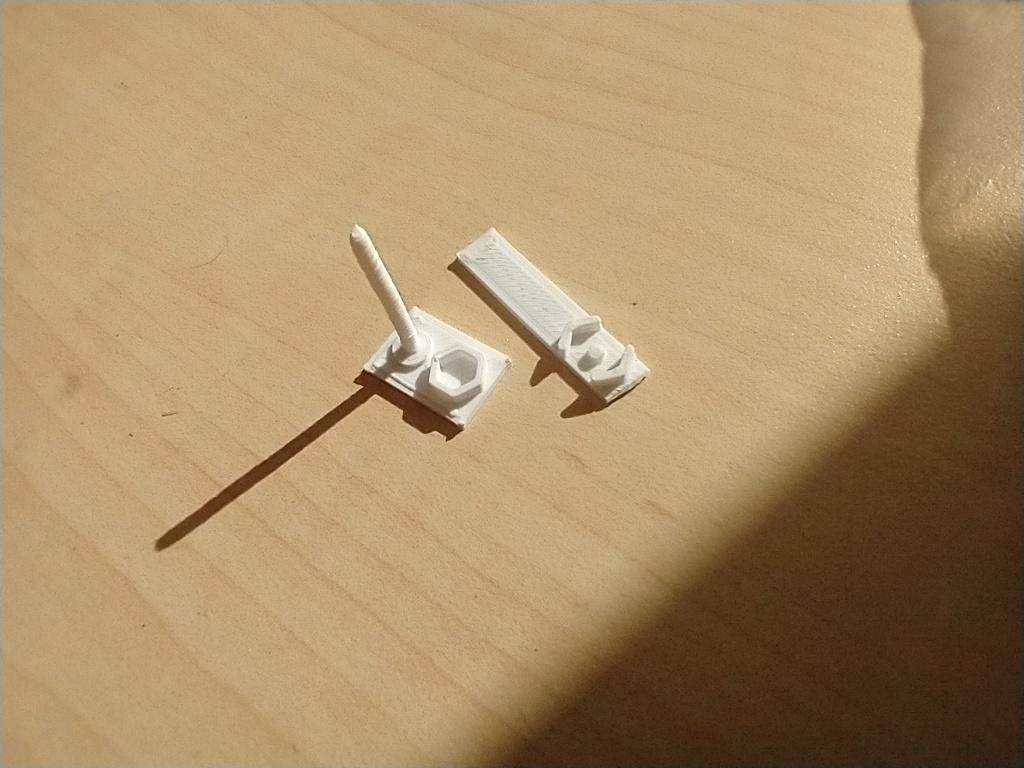
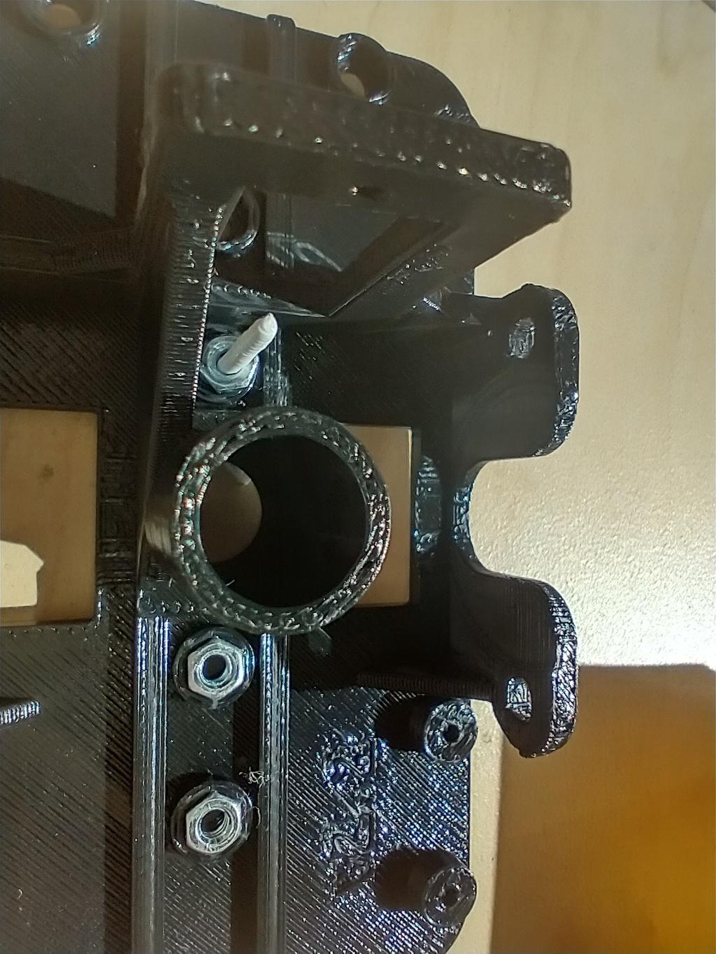
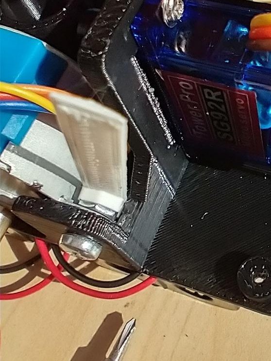
Once printed, assembling the robot was easy enough, except for placing some nuts in very tight places. I designed and printed some 3D-printed tools (OpenSCAD) that significantly eased these tasks.
I wrote Python-based tool to batch update the firmware on the Adafruit ItsyBitsy M4Express used in the OSTR. The tool saves some time (and reset button presses) when updating the firmware.